Hughes EDM maser experimental notes
Non quia facile est, sed quia impossibile est
November 13, 2024

This page will contain notes regarding the hydrogen maser prototype described by Corby Dawson here. I've volunteered to continue a valiant effort that Corby started several years ago: to understand, document, and possibly even resurrect the maser.
(TODO: additional background...)
November 17, 2024
 The Hughes engineering development model ("EDM") was a passive maser at heart, employing a smaller-than-normal cavity. With a Q factor in the 7000-8000 range, a cavity of this type is incapable of sustaining maser action on its own. It would normally have been used as a frequency discriminator with both input and output ports, rather than as a standalone 1420 MHz oscillator in an active maser.
However, the maser's designers borrowed a trick used by amateur radio operators in the days when even a basic quartz crystal filter was a pricy proposition: Q multiplication. By applying a small amount of positive feedback, the
passband width of an IF or RF gain stage can be reduced dramatically without expensive parts, improving both its SNR and ability to reject interference adjacent to the desired signal.
Regenerative receivers had long been built by adding subthreshold positive feedback in the form of a so-called "tickler coil" to a tuned RF stage, so it wasn't much of a stretch for hams in the 1940s to apply the same thinking to one of the IF transformers in a superheterodyne receiver. Likewise,
researchers in the 1980s found that a small maser cavity could operate in a self-sustaining fashion if wrapped in a positive feedback loop.
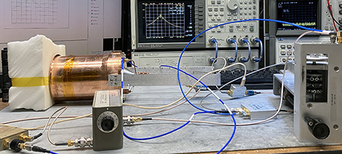
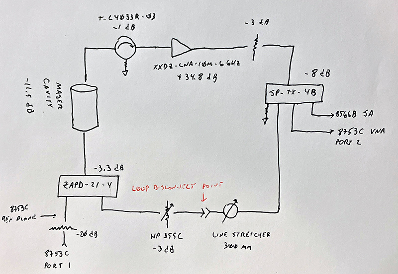
Verifying this principle seemed like a good initial experiment, given that the rest of the physics package won't be back together for some time. The block diagram below was assembled to allow the maser cavity to be
swept with a VNA under both conventional and Q-enhanced conditions:

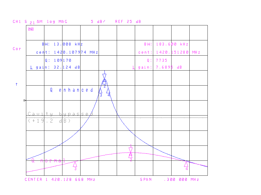
Results were pretty dramatic: with the right combination of loop gain and phase shift, the cavity's effective Q factor exceeded 100,000:

The highest Q obtained in stable operation (i.e., no oscillation observed on the spectrum analyzer between 0-2.5 GHz) was around 130,000. Breaking the feedback loop at the disconnection point returns the cavity to its normal Q factor near 7700.
In the plot above, not only does the cavity's bandwidth increase from 13 kHz to 184 kHz when the loop is opened, but the available signal level at the LNA output decreases by more than 23 dB. Essentially, the cavity's insertion loss of
11.5 dB becomes an insertion gain of almost 13 dB when the loop is closed.
It's also interesting to note that the cavity's center frequency is over 40 kHz lower when Q enhancement is enabled with this particular degree of phase shift. The loop gain has little effect on the center frequency, but the line stretcher can effectively tune the cavity by several kHz without lowering the Q or affecting stability. It's not hard to imagine using a voltage-controlled phase shifter rather than a varactor to perform cavity autotuning, in a
manner reminiscent of the work done by Everard et al. with VCXOs.
Back to John Miles, KE5FX home page
Copyright © 2024 John Miles. All rights reserved.


