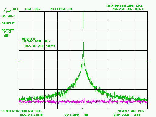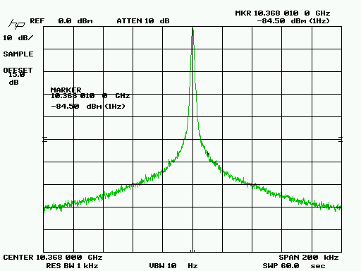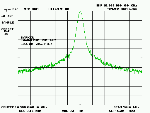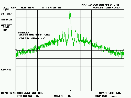
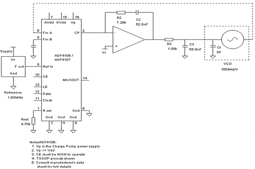
Loop bandwidth is approximately 1 kHz, with loop filter component values specified by ADISimPLL from Analog Devices. The relatively-narrow loop bandwidth was chosen to ensure that measurements were dominated by noise contributions from the Gunn source rather than the PLL.
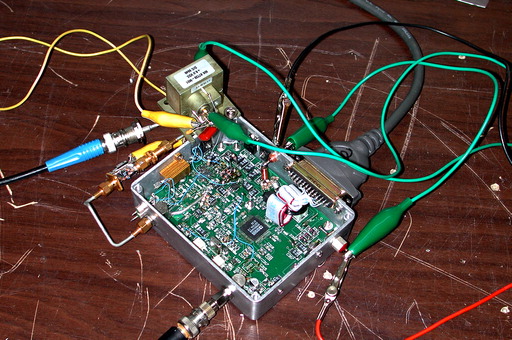
The DDS/PLL assembly in the photo above was originally designed to phase-lock YIG sources between 2 and 6 GHz, requiring the use of an Analog Devices ADF4107 PLL chip. Unlike the 5-volt ADF411x series, the ADF4107 is a 3.3-volt part that requires some modifications to the KE5FX/VK6BRO synthesizer board to operate. However, through the use of an external Hittite HMC363 divide-by-8 prescaler, the PLL chip operates at only 1296 MHz in this application. The more-common ADF4112 or ADF4113 parts would have worked as well, and are recommended for anyone seeking to duplicate this experiment.
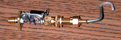
Both the HP 8566B spectrum analyzer and the loop prescaler are coupled loosely to the Gunn source with 1/2" probes in its outer chamber. The signal level at the analyzer's input jack is -15 dBm. The analyzer's noise floor, shown in purple, is approximately 3 dB below the lowest point in the trace in the first plot below (1 MHz span). Consequently, the Gunn source's broadband noise floor crosses the noise floor of the analyzer just beyond the extents shown.
Control software, ADIsimPLL project file, and original HP-GL/2 files may be downloaded here (110K).
